
5 Engineering Design Decisions That Simplify Mining and Large Steel Fabrication
A mining structure can be perfectly calculated and still be painful to build. The difference often sits in early design choices: plate sizes, weld access, lifting points, splice positions, and how the assembly will travel from the workshop to site.
For large steel fabrication, good engineering is not only about strength. It is also about making the job safer, repeatable, and practical for the people cutting, welding, blasting, painting, transporting, and installing the work.
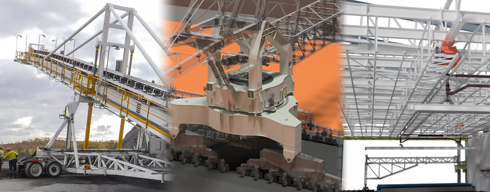
1. Design around transport and site handling from the start
Large mining plant often outgrows the workshop door long before it outgrows the crane chart. Chutes, hoppers, bins, trusses, feeders, tank shells, gantry sections, and support frames can become expensive to move if transport limits are treated as a late detail.
A practical design starts with the maximum transport envelope. That includes width, height, length, mass, centre of gravity, road access, site access, and the crane capacity available at both ends.
For mining and large steel fabrication, this decision affects almost every later step. A structure split into smart modules can move safely, fit through the blast booth, suit available trailers, and reduce site rework.
Good module planning usually considers:
Workshop crane capacity
The part must be turned, held, and loaded without unsafe rigging.
Blast and paint booth limits
Coatings become harder to control when an item barely fits.
Site access
Mine roads, laydown areas, and shutdown windows can limit what is possible.
Final alignment
Splice locations should support accurate fit-up, not create problems at height.
A useful test is simple: can the module be fabricated, coated, transported, lifted, and bolted into position without special rescue plans at every stage?
2. Put splices where they help fabrication and installation
Splices are sometimes treated as a necessary evil. In heavy steelwork, they are often one of the best tools available.
The best splice locations do more than break a structure into smaller pieces. They reduce distortion, give welders clear access, make machining or drilling easier, and place site connections where they can be reached safely.
For example, a transfer chute may be easier to fabricate as a lower wear section, an upper transition section, and a removable hood. A conveyor gantry may suit bolted splice plates at regular bay lengths. A large hopper may need shell segments that allow internal bracing during welding and safe access for lining installation.
The wrong splice can save a little time in the model and cost many hours on the floor. It may land too close to a stiffener, clash with a liner, block a weld, or force awkward overhead work on site.
A good splice design asks three practical questions:
Can the fabricator access both sides of the joint?
Can the part be trial fitted before coating?
Can the site crew install it with normal tooling?
If the answer is no, the splice is probably in the wrong place.
3. Reduce unnecessary plate variety and section changes
Mining steelwork often uses thick plate, heavy sections, and wear-resistant materials. Every extra plate thickness, grade, hole pattern, and section size adds handling, programming, ordering, nesting, and traceability work.
That does not mean every part should be the same. It means the design should avoid variety that does not earn its place.
For example, a chute may not need five close plate thicknesses when two will do the job. A frame may not need multiple near-identical angle or channel sizes. A ladder support, bracket, or gusset may be easier to cut and stock if it follows a common pattern already used elsewhere in the project.
Reducing unnecessary variety can help with:
Material purchasing
Fewer grades and thicknesses reduce ordering mistakes.
Cutting and nesting
Common plate sizes improve yield and reduce offcut confusion.
Workshop flow
Repeated details are faster to mark, cut, drill, and inspect.
Maintenance spares
Mine sites benefit when replacement parts are clear and consistent.
This is especially useful for wear liners, access panels, clamp plates, cleats, and bolted brackets. A small repeatable detail can save time across dozens or hundreds of parts.
The goal is not to make the structure plain. The goal is to make the design buildable without adding complexity that brings no real benefit.
4. Give welders and fitters room to work
A model can show a perfect weld in a corner no hand can reach. It can also show a bolt that fits in space but cannot be tightened with a real spanner. Large steel design must account for tools, hands, heat, distortion, and inspection access.
Weld access should be checked before drawings are issued, not after the first part hits the workshop. This matters on mining gear because thick plate needs proper preparation, controlled welding, and clear inspection paths.
Common problem areas include:
Stiffeners placed too close together
Full penetration welds called up where access is blocked
Gussets that trap welds in tight corners
Bolts located too close to webs or flanges
Wear liners that block later welding or inspection
Clear access reduces rework. It also helps quality inspectors complete visual, magnetic particle, ultrasonic, or other checks where required by the specification.
One practical habit is to review the design from the fabricator’s point of view. If a welder needs to reach into a deep pocket, turn a heavy part three times, or weld continuously around a blocked corner, the design may need a small change.

5. Design holes, slots, and tolerances for real site conditions
Mining sites are not clean laboratory conditions. Foundations move within tolerance, existing steel may not match old drawings, and large assemblies can shift slightly through welding, transport, and lifting.
That makes connection design critical. Holes, slots, packers, shims, and tolerances should reflect how the item will actually be installed.
Bolted connections need enough adjustment to suit site fit-up, but not so much that the final structure becomes hard to align or inspect. Slotted holes can help, but they need proper washer details and clear direction. Base plates may need grout allowance, levelling nuts, or shim space. Conveyor modules may need alignment points that site crews can measure easily.
A few millimetres of planned adjustment can prevent hours of grinding, reaming, or forced fitting during a shutdown.
Designers should pay close attention to:
Existing structure interfaces
Verify what will connect to old steel, concrete, or equipment.
Survey requirements
Nominate hold points where site dimensions should be checked.
Bolt access
Allow room for tightening, torqueing, and later removal.
Coating build-up
Paint and galvanising can affect fit, especially in tight holes and sleeves.
This is where clear drawings matter. The drawing should tell the workshop what must be accurate, what can float, and what the site team can adjust.
The best designs make the workshop look organised
Manufacturing becomes easier when design decisions respect the full path of the steel: detailing, procurement, cutting, drilling, welding, inspection, coating, transport, lifting, installation, and maintenance.
The five choices above sound practical because they are. They reduce surprises. They make work safer. They help teams build large mining structures with fewer delays and fewer awkward fixes.
Strong engineering still starts with load paths, codes, fatigue, wear, and service life. But the best mining fabrication designs also ask a grounded question early and often: how will this actually be made?


Comments